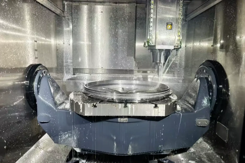
A CNC machine may position very accurately, but that capability only translates into part accuracy when the workpiece is located, supported, and clamped correctly. Poor CNC workholding can allow a part to shift, vibrate, bend under clamp load, or spring back after machining—creating dimensional variation even when the program, tools, and machine are sound.
CNC workholding is therefore not simply a matter of gripping the stock tightly. It is the engineering system that establishes the part’s reference position, resists cutting forces, preserves access for tools and coolant, and makes every loading cycle repeatable. For a simple prismatic aluminum block, a standard CNC vise is often enough. The situation changes when the part has thin walls, deep pockets, irregular geometry, or several critical faces that must remain in the same coordinate relationship.
What Is Workholding in CNC Machining?
Workholding is the method used to position and retain a workpiece during CNC machining. A sound setup has three separate functions:
- Locating establishes where the part sits relative to the machine coordinate system.
- Supporting prevents the part from bending or deflecting under gravity, clamping load, and cutting force.
- Clamping holds the workpiece against its locating and support surfaces.
These functions are related, but they are not interchangeable. A clamp should push a part into its locators; it should not be expected to establish the part’s position by itself.
Workholding directly affects machining rigidity, dimensional repeatability, surface finish, and operator safety, and can also influence tool life by reducing or increasing vibration and deflection. If the workpiece moves under load, the result may be chatter, cutter deflection, inconsistent feature location, poor finish, or damage to the tool and part. Machine accuracy alone cannot compensate for a part that is poorly supported or inconsistently seated.
A fixture is a more specific form of workholding. A standard mill vise, chuck, or clamp is a workholding device. A fixture is usually a purpose-designed or configured arrangement of locators, supports, clamps, and base elements made to hold a particular part or part family in a defined orientation. CNC fixtures become more valuable when repeatability, loading speed, complex geometry, or multiple operations justify the additional effort.

Common CNC Workholding Methods
The appropriate CNC workholding method depends on the part geometry, machining sequence, tolerances, and production requirements. No single approach is universally best.
| Method | Best suited to | Main advantage | Main limitation |
| CNC vise / mill vise | Prismatic blocks, plates, simple machined stock | Fast setup, rigid, economical | Can obstruct side access and distort thin sections |
| CNC clamps | Large, irregular, or oversized workpieces | Flexible positioning and broad capacity | Setup can take longer; clamp placement is critical |
| Chuck or collet | Round, cylindrical, and turned parts | Good concentric holding for rotational work | Radial clamping can distort thin-walled parts |
| Workholding fixture | Repeated, complex, or tight-tolerance parts | Repeatable location, faster loading, better process control | Requires design, build time, and upfront cost |
| Vacuum workholding | Thin plates and broad, flat parts | Clear top-side access and distributed holding | Depends on sealing area and may not resist heavy side loads |
| Magnetic workholding | Ferromagnetic flat stock | Fast loading and unobstructed surface access | Limited to magnetic materials and suitable cutting loads |
A CNC vise remains the most common solution for CNC milling workholding because it is rigid, familiar, and easy to set up. Soft jaws can substantially extend a vise’s usefulness by matching the part contour, increasing contact area, and establishing repeatable locations.
CNC clamps, workholding clamps, and machining clamps are often the practical choice when the workpiece is too large for a vise, has an awkward profile, or needs machining around several exterior faces. The clamp arrangement must still leave room for tools, chips, coolant, and probing.
Chucks and collets suit cylindrical work, especially on CNC lathes. Collets generally provide more uniform contact for smaller-diameter parts, while chucks offer broader size capability. For thin tubes or delicate rings, radial clamping needs careful control because gripping force can create out-of-roundness before cutting even begins.
CNC workholding fixtures are usually selected when standard workholding devices cannot achieve the needed repeatability, access, support, or loading efficiency.
How to Choose Workholding for a CNC Part?
A useful selection sequence is:
Part geometry → machining forces → datums → tolerance → tool access → production volume
The part comes first; the workholding method follows the part.
Start with the geometry
A simple rectangular block with accessible top and side features can often be machined in a CNC vise. A large casting, plate, or irregular forged component may need CNC clamps on a fixture plate. A shaft, hub, or circular component generally points toward a chuck, collet, mandrel, or dedicated turning fixture.
The geometry also changes as material is removed. A rigid billet may become flexible after deep pockets are opened or after thin walls are machined. The workholding plan should reflect the part’s stiffness at each machining stage, not only the starting stock shape.
Evaluate cutting forces and force direction
Clamping force must be high enough to resist the expected cutting loads, but not so high that it deforms the workpiece. “Clamp harder” is rarely a reliable answer.
For example, a thin aluminum wall may meet drawing dimensions when unloaded but distort under excessive jaw pressure. If the wall is machined while deflected, it can move when the part is released. The machined feature may then be out of position, bowed, or inconsistent even though it appeared correct while clamped.
Place clamps so their force pushes the workpiece toward locating surfaces and through well-supported regions. Avoid clamping over unsupported pockets, thin ribs, or open cavities where the clamp can bend the part.
Establish practical datums
Where practical, subsequent operations should locate from drawing datums or functionally important features. This helps preserve the dimensional relationships that matter to assembly: a bore relative to a mounting face, a pocket relative to a sealing surface, or a pattern of holes relative to a locating edge.
If a first operation creates a critical datum surface, a later operation may use that surface for location rather than relying on raw stock. This reduces the accumulation of variation between operations.
Match workholding to tolerance and access
Tight positional tolerances often require a stable datum scheme and repeatable seating. A part may fit in a standard vise, but the vise may not provide enough access to machine all critical features without multiple reclamps. Each re-clamp introduces another opportunity for position error.
Tool access is equally important. Fixtures, clamps, and jaws must not block the cutter path, toolholder, spindle, coolant stream, or probe. In 5 axis CNC workholding, clearance becomes even more important because the spindle and rotary axes need room to approach the part at different angles.
Consider production volume
For a one-off prototype, standard workholding is often more economical because setup flexibility matters more than loading speed. For repeated production, workholding fixtures can reduce setup time, loading variation, and operator dependence. In higher-volume production, a fixture may also support automation, palletized loading, multi-part setups, or inspection routines.
 How Does 3-2-1 Locating Improve CNC Machining Accuracy?
The 3-2-1 locating principle is a practical method for positioning a rigid part without over-constraining it. A workpiece has six degrees of freedom: movement in X, Y, and Z, plus rotation around each axis. The fixture controls these degrees of freedom through three sets of locating points:
- Three points support the primary datum plane.
- Two points establish the secondary datum plane.
- One point establishes the tertiary datum plane.
For example, imagine a machined rectangular plate. Three support pads under its bottom face establish the primary plane. Two side pins locate one long edge, and one end stop establishes the final position. The clamps then push the plate down onto the pads and sideways against the pins.
This arrangement typically constrains the part without forcing it to conform to too many contact points. The primary plane controls vertical movement and two rotations; the secondary plane controls one lateral movement and rotation; the tertiary point controls the final lateral movement. This six-point approach is widely used to control all six degrees of freedom while avoiding unnecessary constraint.
Over-constraining can cause inconsistent loading. For example, if a real part has normal thickness variation, burrs, minor casting variation, or slight surface waviness, too many fixed locating points may prevent it from seating the same way every time. The result can be rocking, forced distortion, or an operator-dependent setup. The practical goal is to constrain the required degrees of freedom—not to add locators indiscriminately.
Workholding Challenges for Thin-Walled and Complex Parts
Thin-walled and complex components expose the difference between holding a part securely and holding it without changing its geometry.
A deep-pocketed aluminum housing may begin as a stiff block, then lose much of its rigidity after roughing. If clamps bear directly over thin floor sections or open cavities, the part can flex under clamp load. When the fixture is released, the part relaxes. Critical faces or walls machined in the distorted state may no longer meet flatness, position, or wall-thickness requirements.
Common issues include:
- Excessive clamping force causing local deformation or spring-back.
- Insufficient support allowing vibration, chatter, and tool deflection.
- Deep pockets and tall walls reducing stiffness as machining progresses.
- Irregular geometry providing few natural locating surfaces.
- Multiple orientations increasing re-clamping error and setup time.
- Clamps, jaws, or fixture structures blocking tools, coolant, or chip flow.
Practical responses depend on the part and process:
- Support the workpiece close to the cutting zone, especially beneath thin floors or around heavy milling areas.
- Distribute clamping force over a larger contact area with soft jaws, contoured supports, or suitable clamp pads.
- Use soft jaws to conform to nonstandard external geometry and reduce point loading.
- Add locating pads, sacrificial tabs, temporary process features, or custom locating features where the part design permits.
- Sequence machining so the part retains stiffness during major stock removal, then finish sensitive geometry with lower cutting and clamping loads.
- Include fixture relief for tools, chips, and coolant rather than making every fixture surface tightly conform to the part.
A fixture pocket or locating feature must also account for the internal radius left by machining tools. A sharp-cornered part will not seat fully in a pocket if the pocket contains an unaccounted-for internal corner radius. The part may appear clamped but actually sit high, rock on corner contact, or locate inconsistently. Adding appropriate corner relief prevents this interference.
Vacuum workholding can be useful for thin, flat parts because it spreads holding force over a broad area and leaves the top surface relatively clear. However, it is not automatically appropriate for heavy milling, tall parts, porous materials, or geometry with limited sealing area. Similarly, CNC magnetic workholding can provide fast access for ferromagnetic plates, but it must be matched to the material and expected cutting forces.
A practical example is a thin-walled PEEK racing wheel, where controlled workholding and temporary internal support were used to protect a 0.5 mm rim during final machining.
When Do You Need a Custom Workholding Fixture?
Standard workholding is sufficient when it locates the part reliably, provides adequate support, allows safe tool access, and does not create excessive setup time. A custom solution becomes worthwhile when those conditions cannot be met consistently.
Custom workholding fixtures are often justified by one or more of these conditions:
- Complex geometry with few usable flat or parallel surfaces.
- Tight tolerances between features machined in different orientations.
- Repeated production requiring reliable loading and consistent work offsets.
- Multiple setups that create unacceptable accumulated location error.
- High setup time caused by manual indicating, packing, or clamp adjustment.
- Thin, flexible, or irregular parts that need contoured support.
- Difficult or unsafe loading with standard workholding devices.
- Automation, palletization, multi-part loading, or in-process probing requirements.
The decision is economic as well as technical. Workholding fixture design adds cost, lead time, and maintenance responsibility. For a prototype or a low-value one-off part, a CNC vise, clamps, soft jaws, or a simple fixture plate may be more economical. For repeated production, custom workholding can lower setup time, improve repeatability, reduce scrap risk, and make the process easier to run consistently.
A dedicated fixture does not need to be elaborate to be useful. A pair of contoured soft jaws, a locating plate with pins and supports, or a simple custom fixture may solve the real manufacturing problem. More complex CNC machining fixtures are justified when the part value, production volume, or process risk supports the investment.
For engineering-oriented machining suppliers, this is where early DFM discussion matters: a part can be designed for function while still including practical features that improve location, support, probing, and machining access.
CNC Workholding Design Checklist
Before releasing a part for machining or approving a fixture concept, review these points:
- Locate from drawing datums or functionally critical features where practical.
- Separate locating from clamping; clamps should seat the part against locators.
- Provide support beneath areas exposed to significant cutting or clamping loads.
- Use only the locating constraints needed for stable, repeatable seating.
- Control clamping force to resist cutting loads without distorting the part.
- Keep cutting tools, toolholders, probes, coolant, and chip flow clear of clamps and fixture walls.
- Add fixture relief for cutter radii, internal corners, part transitions, and chip evacuation.
- Make loading repeatable with clear datum contacts, positive stops, and practical operator access.
- Confirm that critical features can be probed or inspected without unnecessary re-clamping.
- Define machine alignment, work offsets, and setup orientation so the CNC program references the intended datums.
FAQ
What is CNC workholding?
CNC workholding is the system used to locate, support, and clamp a workpiece during machining. It can include a CNC vise, collet, chuck, clamps, soft jaws, vacuum table, magnetic table, or dedicated fixture. Its purpose is not merely to stop movement; it must position the part repeatably while resisting machining forces without causing unnecessary deformation.
What is the most common CNC workholding method?
For CNC milling, a standard CNC vise or mill vise is one of the most common workholding methods because it is rigid, quick to set up, and suitable for many prismatic parts. Soft jaws, parallels, stops, and simple fixture plates extend its range. Larger, irregular, round, thin, or repetitive parts often require other workholding solutions.
How do I choose a workholding method for a CNC part?
Start with the part geometry and the surfaces that must serve as machining datums. Then evaluate cutting-force direction, wall stiffness, tolerance requirements, tool access, number of setups, inspection needs, and production volume. A workholding method is appropriate when it locates the part consistently, provides enough support, permits safe machining access, and fits the economics of the production run.
When should I use a custom workholding fixture?
Use custom workholding when standard vises, clamps, or chucks cannot provide repeatable location, adequate support, tool access, or efficient loading. It is often worthwhile for recurring parts with complex geometry, thin walls, tight tolerances, difficult multiple setups, or automation requirements. For one-off prototypes, standard workholding is often the more economical starting point.
Can workholding affect CNC machining accuracy?
Yes. CNC workholding can strongly affect accuracy because poor location, insufficient support, excessive clamping force, or inconsistent seating can cause movement, deflection, chatter, and spring-back. A machine may execute the programmed toolpath accurately while the part itself shifts or distorts. Good workholding preserves the datum relationships and stiffness needed for the finished part to meet its drawing requirements.
Need help planning workholding for a complex CNC part?
FastPreci can review your part geometry, machining requirements, and production volume to determine whether standard or custom workholding is appropriate.